
Supporting materials
Download
Download this article as a PDF


Through the looking glass: unlock the secrets of anamorphosis, where art and science meet to create mind-bending illusions!
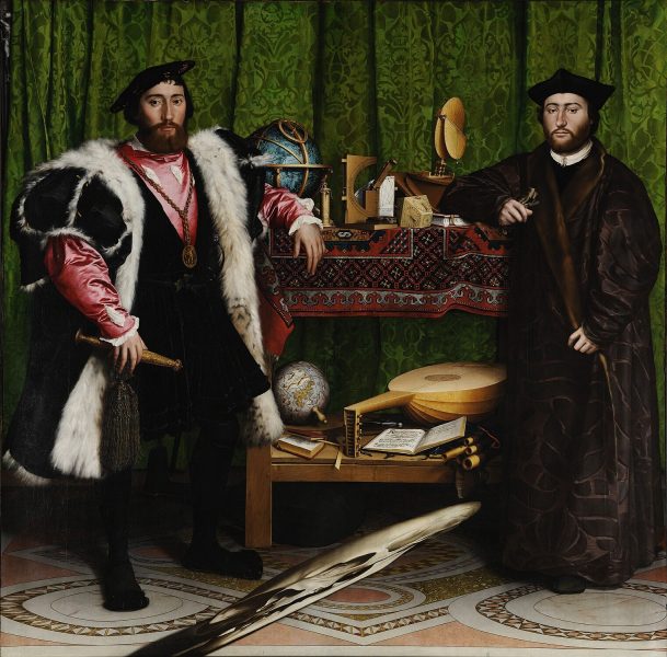
Anamorphosis – a term derived from the Greek words ‘ana’, meaning ‘back’, and ‘morphe’, meaning ‘form’ – essentially refers to a visual technique that distorts an image in a way that it can only be fully perceived when viewed from a specific vantage point or with the aid of a particular device. This phenomenon has intrigued artists and scientists alike for centuries, and offers a fascinating journey into the world of distorted images and optical illusions, with famous examples like Hans Holbein’s The Ambassadors, where a skull is only visible if you look at the painting at an angle, and Leonardo da Vinci’s anamorphic eye drawings.[1]
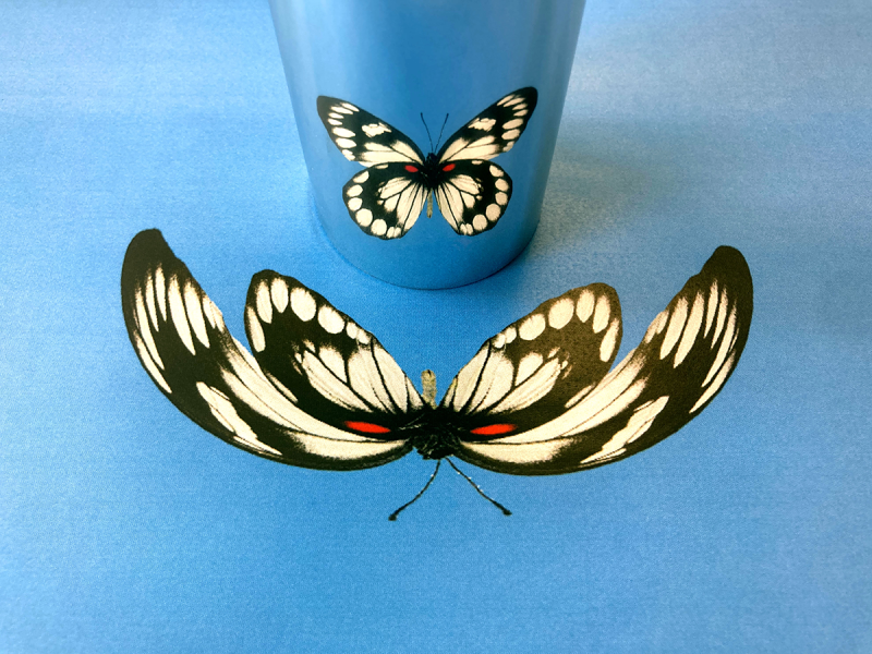
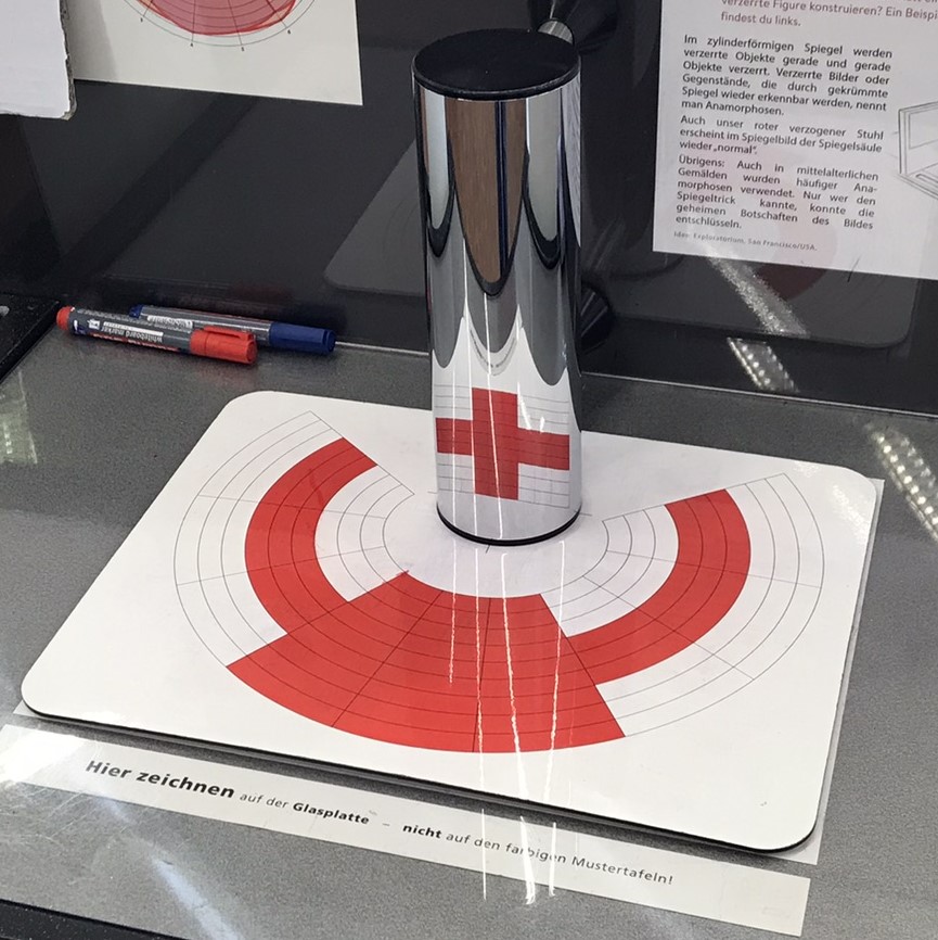
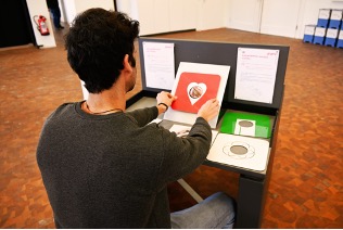
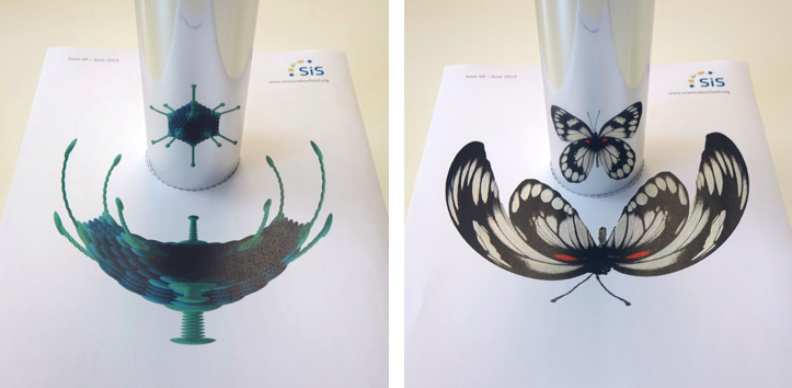
One of the most intriguing methods of creating anamorphic images is to use mirrors. When an image is painted onto a flat surface and viewed on a cylindrical mirror placed next to it, for example, the distorted elements ‘magically’ transform into a coherent, recognizable image. Last year, the Mathematik-Informatik-Station (MAINS) in Heidelberg hosted the exhibition Faszination Spiegelwelten (fascinating mirror worlds),[2] and the following activities are based on some of the stations in the exhibition.
Anamorphosis provides an excellent opportunity to combine concepts from physics, mathematics, geography, and art in an engaging way. These activities use cylindrical mirrors to provide examples for exploring optics with curved mirrors (Activity 1) and coordinate transformation and geometry (Activity 2), with a final activity to engage students in creating their own anamorphic visual art (Activity 3). More complicated topics for advanced students are also suggested.
All of the activities require the use of a cylindrical mirror (ideally one per group of students) that is around 15–20 cm high. The images provided in the supporting material for printing are optimised for a mirror that is 17 cm in circumference (around 5.4 cm in diameter), but other sizes can be used. You will just need to move the mirror closer or further away from the image to get a good result.
Cylindrical mirrors can be ordered from an education supplier, improvised from highly reflective metal tubes or pipes (e.g., from a DIY centre), or constructed using reflective film, as detailed below.

Roll up the film so that the outside edge lines up with the 17 cm mark, and tape it to create a cylinder with a circumference of 17 cm.
With a support: measure and mark out a rectangle of reflective film that is approximately the height of the support and with a length at least 3 cm longer than the support circumference.

Roll the film around the support and tape or glue in place.
Assuming students have a basic understanding of reflection on plane mirrors, this activity can be performed as an in-class demonstration by a teacher to introduce optics with a curved mirror. Students are encouraged to predict, observe, and explain what is happening using their base knowledge. The demonstration takes less than 5 minutes, and the discussion takes 10–20 minutes.
| Property of reflection from a flat surface | Applies | Does not apply |
| The image is virtual. | X | |
| The image is of the same size as the object. | X | |
| The image is laterally inverted, meaning that images are not reversed from top to bottom, but are reversed from left to right. | X | |
| The distance between the image obtained from the mirror is the same as the distance between the object from the mirror. | X | |
| The angle of incidence and the angle of reflection are always equal. | X | |
| The incident ray, the normal at the point, and the reflected ray all lie on the same plane. | X |
After working through the exercise, the students should discuss why they observed the results they did. If necessary, the teacher can unveil the magic behind the scenes, but older students may be able to work it out for themselves by drawing ray diagrams for a convex mirror.
Students should first understand that, locally, curved mirrors can be understood as behaving like plane mirrors, with each ray reflecting from the point it hits the mirror, as if that point was the plane that formed the tangent to the curve at that point. By drawing several light rays to a curved mirror and following their paths, students should be able to see how the image becomes distorted. The teacher may introduce the concept of focus, focal length, and so forth.

The teacher may also use computer simulations for illustration, for example, this ray optics simulation from PhyDemo or this concave and convex mirrors simulation from oPhysics.
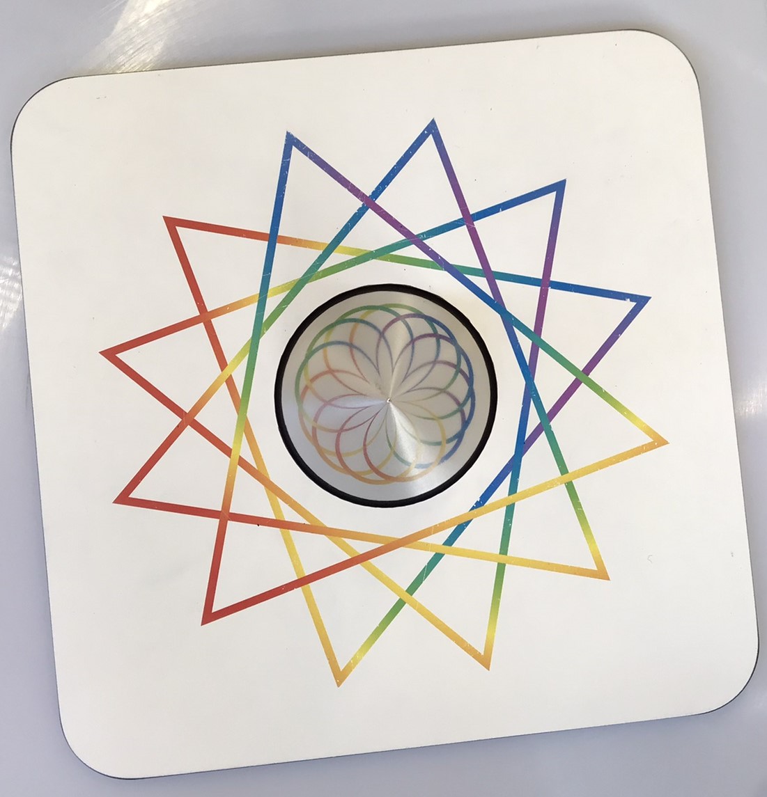
An optical explanation for the conical mirror is rather complicated to draw. For further information, teachers can refer to https://anamorphicart.wordpress.com/2010/04/21/conical-mirror-anamorphoses/.
As a continuation of Activity 1, in this activity, coordinate transformation is briefly studied, with more advanced geometry as an optional addition. The experiment itself only takes a few minutes, but the discussion can take 10 minutes or much longer, depending on how much detail is discussed.
Note that, generally, coordinate transformation refers to a change of description, and the object remains the same. In this sense, imaging using a cylindrical mirror is not a true coordinate transformation but a geometric transformation, but the explanation here primarily serves to prepare for Activity 3, where the students transcribe a picture from one coordinate system to another.
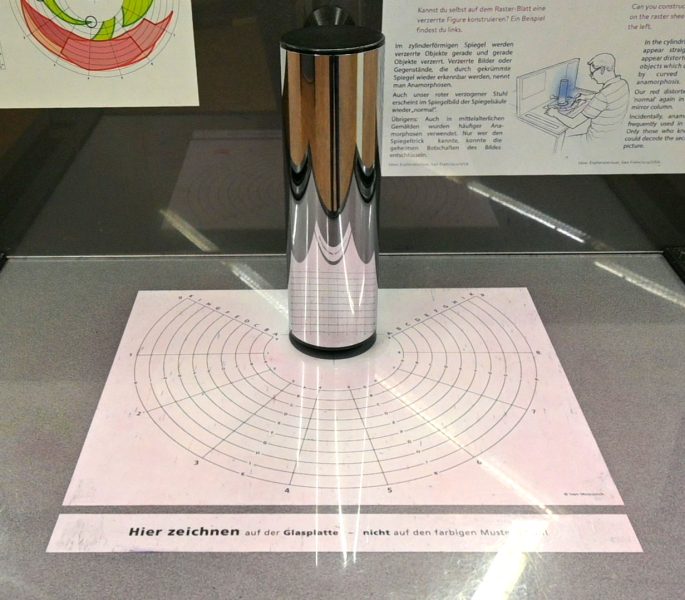
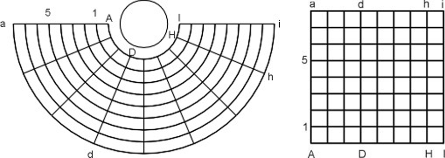
Remind the students of the question from Activity 2: are all parts of the images distorted equally? With the aid of a coordinate system, one can describe distances in unit length, allowing for a quantitative assessment of the degree of distortion.
These results can act as a basis for a discussion on geometric transformations or coordinate systems. The link to coordinate systems is particularly interesting since it links to the real-world problem of cartography.
A coordinate system is a method for identifying the location of a point. On a two-dimensional surface, coordinate systems use two numbers, a coordinate, to identify the location of a point. Each of these numbers indicates the distance between the point and some fixed reference point, called the origin.
A known example is the geographic coordinate system, which is the spherical coordinates of latitude and longitude.
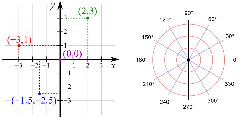
The Cartesian, or rectangular, coordinate system consists of an origin, a horizontal x axis, and a vertical y axis. The point where the axes cross is the origin. Any point can be described by the horizontal distance from the y axis (x), and the vertical distance from the x axis (y); together these are written as (x, y). The origin is written as (0, 0). The coordinates can be read more conveniently with the help of a grid, where lines are drawn parallel to the axes.
For the polar system, only one axis and an origin are needed to define the measurement of distance and the reference direction. The coordinates are given by the distance from the origin (r), and the angle from the positive x axis (θ).
To convert from polar to Cartesian coordinates:

To convert from Cartesian to polar coordinates:

This kind of transformation, which involves preserving the angle but not lengths, is known as conformal mapping, a concept that is essential in mathematics and theoretical physics, and more practically, a technique employed in cartography to address the challenge of showing a curved planet on rectangular maps.
There are many different types of map projections and they all preserve different features of the globe, but no map from the sphere to the plane can be both conformal and area preserving; they all produce some kind of distortion. The best projection to use depends on the context.
This discussion can illuminate how common types of world map, like the Mercator projection, distort the true sizes of continents and oceans, thereby emphasizing the significance of understanding transformations. You can use thetruesize tool to explore how the Mercator projection distorts country sizes.
Armed with an understanding of coordinate transformations and the magic of curved mirrors, students are given the task of creating their own anamorphic artwork.
To add depth to this activity, the teacher can encourage students to consider other artistic implications of anamorphosis. How can they use these principles to create mind-bending illusions in their artwork? This activity not only reinforces the concepts learned but also sparks creativity and artistic expression.
This activity takes 30 minutes.
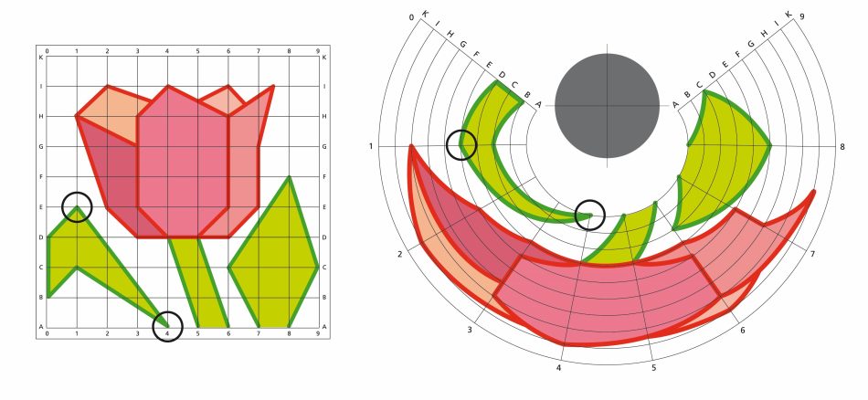
It is also possible to convert digital images to a polar coordinate system using software tools. This can be done in Photoshop using the ‘warp’ function (see the Photoshop instructions), although this gives only a simple semi-circular arc. A better alternative is the tool AnaMorph-It, which converts images to an optimal arc for use with a cylindrical mirror, and the free version can be used for creating and printing images. With these tools, students can create their own anamorphic images for cylindrical mirrors, using photos of their own artworks or other things that interest them.
The teacher may also encourage students to look up the artwork of M. C. Escher to explore other kinds of optical illusion, including impossible objects, in art.
The idea for this article originated from the exhibition The Fascinating World of Mirrors that was on display at MAINS in Heidelberg, Germany, in 2023. The exhibits were displayed in collaboration with the Science Center phaeno in Wolfsburg, Germany, where the exhibits, developed by Technorama, had been displayed previously.
MAINS was established by the Heidelberg Laureate Forum Foundation in 2017, with the goal of promoting awareness, interest, and understanding of mathematics and computer science by the public. Throughout the year, they offer various activities for all age groups, such as interactive exhibitions, an annual film festival, Science Notes, lectures, and workshops. They also offer guided tours of their exhibitions for school classes and groups.
[1] Faust M (2018) “Eyed awry”: blind spots and Memoria in the Zimmern Anamorphosis. Journal of Historians of Netherlandish Art 10. doi: 10.5092/jhna.2018.10.2.2
[2] Webpage of the exhibition Faszination Spiegelwelten (fascinating mirror worlds) on the MAINS website: https://www.heidelberg-mains.org/en/exhibitions/archive/the-fascinating-world-of-mirrors.html.
Yajie Liang is a master’s student at the Institute for Theoretical Physics in Heidelberg, where she studies cosmic structure formation and gravitational theories. She works at MAINS part time, where she gives tours through exhibitions in mathematics and computer science, and answers questions from visitors.

Shine a light on the science of colour: create and combine rainbows and explore how colours arise through reflection, absorption, and transmission.


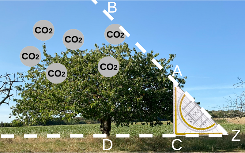
Biology, maths, and the SDGs: estimate the CO2 absorbed by a tree in the schoolyard and compare it to the CO2 emissions of a short-haul flight.
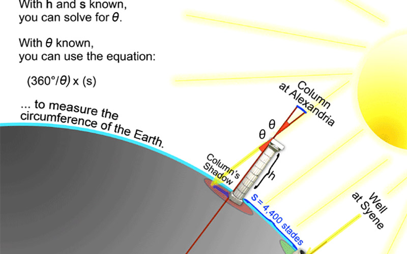
On the shoulders of giants: follow in the footsteps of Eratosthenes and measure the circumference of the Earth like he did 2300 years ago.

