Introducing block coding: using the BBC micro:bit in the science classroom Teach article

Always wanted to do coding with your students but not sure where to start? Learn how with this step-by-step guide to create a timer using a micro:bit computer.

Numerous small, inexpensive single-board computers (SBCs) have been developed to get students interested in coding and computer science. A recent entry – the BBC micro:bit – has broad application in various other subject areas, particularly science classrooms.

This article is a brief introduction to coding the micro:bit, with step-by-step instructions for 11–16-year-old students to use block code to create a tool (a timer) that can be used in science investigations. The coding activity should take 45 min or less.

Figure 1: Front and back of micro:bit (version 1)
Image courtesy of G. Michael Bowen

micro:bit

The micro:bit was created by a consortium of companies to develop a small, inexpensive computer that could be easily used by middle-school students. micro:bits are now used by students around the world, and in some countries (such as the UK and Canada) they are actively promoted for use in schools by education authorities.

Image:   Aruld/Wikipedia, CC BY-SA 4.0

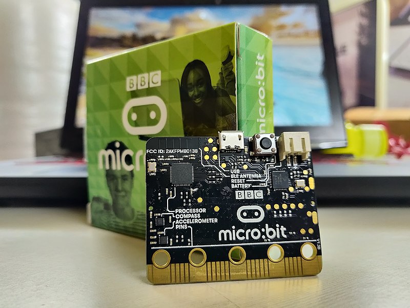
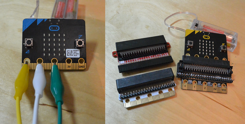
Only slightly larger than a pack of matches, the easily programmable micro:bit costs about €25. Apart from the low price, the micro:bit has at least three other features that make it particularly appealing to a middle-school teacher:

  1. The block code programming tool, MakeCode, is available online, is free of cost, runs in a web browser, and is graphical and easy to use (it is similar to Scratch, which many students also learn). The micro:bit is plugged into a computer using a micro-USB cable, and programs can be saved directly to it, since it appears as an external drive. The programming tool includes a graphical micro:bit emulator, which allows students to test their code with a browser before they use it with the micro:bit. This also allows teachers to use the programs we describe here without having a micro:bit.
  2. Micro:bits have several built-in sensors (compass/magnetometer, accelerometer, thermometer, light detector), two input buttons, and a 5 × 5 light-emitting diode (LED) matrix output screen, allowing the micro:bit to be used for science investigations right out of the box (see figure 1). The recently released version 2 micro:bit also has a microphone, a small speaker, a touch-sensitive area/switch, an LED power indicator, and can be powered off. The programming code in this article will work with either version.
  3. The micro:bit is easily expandable. Add-ons can be attached using alligator clips or by using an adapter that allows more complex circuits, sensors, and screens to be attached to and controlled by it (figure 2). Many robot and science, technology, engineering, and mathematics (STEM) sensor kits are also available.
Figure 2: Alligator clips (left) to add devices and expansion boards (right) to add devices/components
Image courtesy of G. Michael Bowen

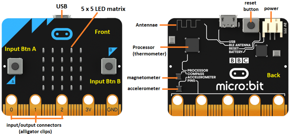
New micro:bits initially run a short, preinstalled, introductory program that familiarizes the user with the input buttons, the LED matrix, and the accelerometer (which detects motion and tilting) when you first attach it to a power source. [see https://www.youtube.com/watch?v=HYLDzqWb9Xs for version 1]

Notes on programming the micro:bit

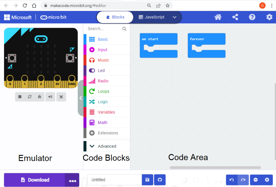
The browser-based programming tool available for the micro:bit has a graphical micro:bit emulator on the left, block code programming options near the centre, and the programming area where code blocks are placed on the right (figure 3). More advanced users can program the micro:bit using text-based languages, such as Javascript or Python (in the MakeCode interface), and there are also other programming environments, such as C and Scratch.

Figure 3: Home screen of the MakeCode programming tool in the browser
Image courtesy of G. Michael Bowen

To demonstrate the basics of coding, we have created a program using coloured block code to create a timer that could be used in science inquiry investigations.

For this task, the micro:bit accepts inputs (in this case, buttons A and B being pressed), follows the instructions of the program and processes the information recorded when these inputs are pressed, and will then provide output on the 5 × 5 LED screen.

When you create a program, you need to first make design decisions about what inputs are needed, how those inputs will be processed, and what outputs will occur. Then you can decide how the code will accomplish them.

There are many ways to design a timer tool and to create the code for the micro:bit, and we present one example. We based our approach on the following requirements and considerations.

Requirements

  • Indicators on the 5 × 5 matrix to show that the program has started properly, when the program is ready for initial input, and when the timer has started
  • Inputs to start and stop the timer
  • An input to show the output (i.e. elapsed time)
  • An input to reset the timer

Considerations

  • There are only three input button options (button A, button B, button A+B)
  • The 5 × 5 matrix can only show one number or letter at a time – scrolling is slow

Programming a timer

The timer code uses blocks for inputs, outputs, and variables. Code for the timer also includes what is called a conditional statement (if x, then do y; otherwise, do z) and formats the numeric output to include units.

The timer needs to perform four functions: 1) start time, 2) stop time, 3) show elapsed time, and 4) reset. However, there are only three button input options, so we need to use one button for two functions. This is done by defining three variables and using one button as a start/stop toggle.

We decided to both start and stop the timer by pressing button A. Variables are created to allow button A to be used to toggle the timer code on and off (variable ‘timer’) and to record the start and finish time. The elapsed time is displayed by pressing button B, which results in the elapsed time being scrolled across the 5 × 5 LED matrix.

<CODING TIP> A variable is essentially a named storage container, and you create them under the ‘Variables’ menu. In this program the variables all hold number values.

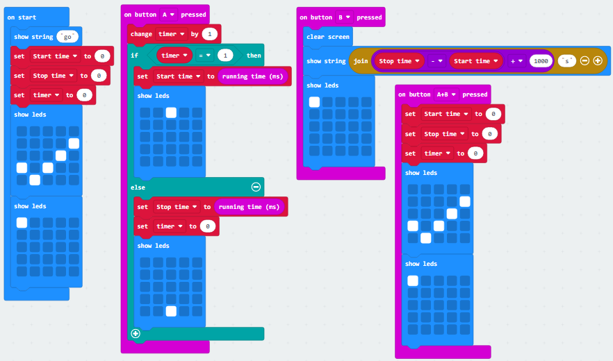
The timer program itself has four columns of code instructions, which are individually described below.

Materials

  • Laptops/Chromebooks for each pair of students
  • micro:bit for each pair
  • Micro-USB cable to connect the micro:bit to the computer

Procedure

The timer relies on the ‘running time (ms)’ function that is built into MakeCode. It counts the time in milliseconds since the micro:bit was started and is reset by restarting the micro:bit (or by pressing the reboot button on the back). Below are descriptions of the final code. Detailed instructions for the timer program are provided in the supporting material.

Code block 1: Starting the program and initializing variables

Figure 4: Starting the program; initializing the variables
Image courtesy of G. Michael Bowen

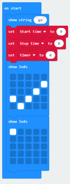
The purpose of this set of code blocks is to set the starting value of the variables that have been created and to tell the user that the micro:bit is ready to accept input.

  1. The ‘on start’ block runs first when the micro:bit is started. The code blocks in the on start ‘jaw’ are the first to be run when the micro:bit is turned on.
  2. The ‘show string’ block holds the text that scrolls across the 5 × 5 LED matrix when the program starts. It is optional. Some alternative timer code modifications are provided in the supporting material.
  3. There are three variables that have been created, which are named ‘start time’, ‘stop time’, and ‘timer’.
  4. The red ‘set’ block is dragged over to the on start block three times, and each one is set to one of the three variables. The starting value for each is set to zero. These ‘set’ blocks initialize the three variables. It is important to initialize variables at the start of a program.
  5. The two ‘show led’ blocks show that the program has started well (the check mark) and is then waiting for input (top-left LED is lit; figure 4).

Code block 2: Starting and stopping the timer function

Figure 5: Recording the start and stop times in variables
Image courtesy of G. Michael Bowen

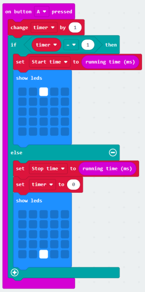
The purpose of this set of code blocks is to put the starting time and finishing time into two different variables, so that the elapsed time can be calculated. This code toggles the value of the ‘timer’ variable between 0 and 1, so that button A can be used to both start and stop the timer using a ‘conditional’ statement. The bottom-centre LED being turned on lets you know there is a recorded elapsed time to see (figure 5).

  1. The ‘on button’ block has jaws that hold the code blocks that are run when button A is pressed.
  2. The ‘change timer’ and ‘set timer’ blocks toggle the value of the variable timer.
  3. The ‘if’ block has two jaws with different code blocks in each of them. If the timer variable has one value, then it does one thing; if it does not have that particular value, then it does the other thing. This is known as a conditional statement.
  4. If the timer is being started by pressing button A, the if block records the current running time in the ‘start time’ variable, and the top-centre LED is turned on. If the timer is already running and button A is pressed, then the current running time is recorded in the ‘stop time’ variable, and the bottom-centre LED is turned on (and the top-centre LED is turned off).
  5. The bottom-centre LED being turned on lets the user know that there is an elapsed time, which they can see by pressing button B.

Code block 3: Calculate and show elapsed time

Figure 6: Calculating and showing the elapsed time
Image courtesy of G. Michael Bowen

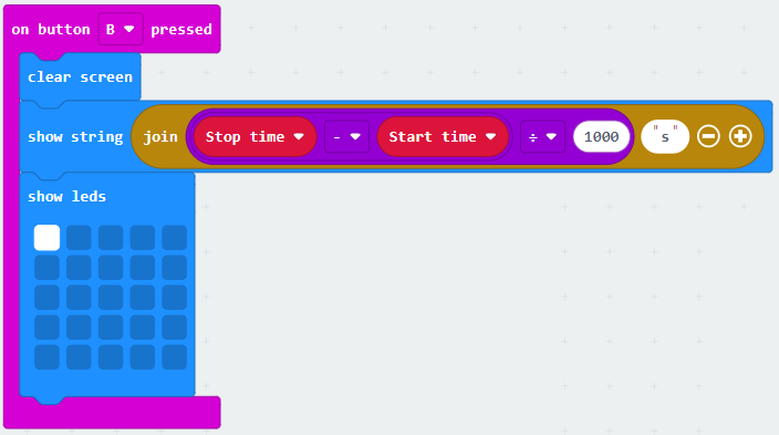
The purpose of this set of code blocks is to calculate and show the elapsed time (figure 6). A decimal may also be shown scrolling across the second row from the bottom if there are fractions of seconds. Note: the micro:bit does not show trailing zeroes, so an elapsed time of 3.40 s is shown as 3.4 s.

  1. The ‘on button’ B code block runs the code inside its jaws when button B is pressed.
  2. The 5 × 5 matrix is cleared. The second code line in the jaws is a series of embedded blocks that show the elapsed time with the letter ‘s’ for the unit seconds. The elapsed time is calculated by subtracting the starting running time (recorded in variable ‘start time’) from the running time recorded in variable ‘stop time’ when button A is pressed the second time. This difference is then divided by 1000 to convert from milliseconds (i.e. thousandths of a second) into seconds. To compensate for how the ‘show’ block works, the calculated time in seconds is then joined onto the letter ‘s’ before being scrolled across the 5 × 5 LED matrix using ‘show string’.
  3. After the elapsed time and units are scrolled across the screen, the upper-left LED is turned ‘on’, indicating the timer is ready to be used again.

<CODING TIP> When a series of code blocks are embedded in each other, then they are enacted in order from the innermost one to the outermost. In the case of showing the elapsed time, this means the arithmetic difference is calculated first, then it is divided by 1000, the letter ‘s’ is joined onto the number, and then that information is shown using ‘show string’.

Code block 4: Reset variables to zero

Figure 7: Reinitializing the variables
Image courtesy of G. Michael Bowen

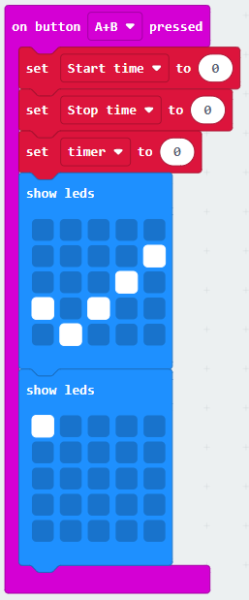
The ‘button A+B’ block resets all of the variables to zero, so the timer can be used again (figure 7). When this is done, pressing button B shows a zero. If you do not reset the variables, you can get some funny-looking outputs the second time you use the timer. Specifically, the second time you used the program, if you pressed Button A only once and then Button B to show output, you would see a negative time scroll across the screen. A teacher could have their students notput this block into their code, then demonstrate obtaining a negative time and ask the students how they could create code to stop that from happening.

Putting it all together

When you’ve entered all four blocks of code, your screen should look something like this:

Figure 8: Timer program blocks of code
Image courtesy of G. Michael Bowen

We have provided a web-accessible version of the program and there is also a YouTube video of the program being used.

Once you have your program coded and working using the emulator, it is time to download the program onto the micro:bit. Instructions on saving the hex code program to your computer and the micro:bit are provided in the supporting material.

Discussion

This timer program is not as accurate as a dedicated stopwatch would be, because running the code itself takes time and the LEDs have a short time lag associated with them. This is why rapidly pressing button A twice does not give a time below 0.4 s. This could be compensated for by subtracting 0.4 s from the time, or it could be discussed with students and they could propose a solution. Removing the LED blocks (in the second column of code) can also make the timer more accurate. We have left the code with the ‘lag’ as an example of a design decision that makes a trade-off related to performance. There are advantages to allowing students to deal with messy data.[1]

Extension activities

Various studies can be done using this micro:bit timer, for example:

  • Rolling a toy car down a ramp at different angles and measuring the time it takes for the car to get to the bottom of the ramp.
  • Recording how long it takes to dissolve sugar at different water temperatures.

Here are some simple programming challenge ideas that build on the coding skills developed in this timer coding activity:

  • Use an external switch for the timer.
    The micro:bit can function much like a Makey Makey. You can connect an external switch made from various conductive items to trigger the timer start and stop it using the appropriate code for connecting it to pin 0/1/2 and ground (‘on pin’ found under ‘input’). This effectively increases the number of input options available from three to six.
  • Make a countdown timer instead of a count-up time.
    The timer we coded in class is a count-up timer, meaning it will tell you how long an activity takes. Challenge: make a timer that is a countdown timer, meaning the user can input a time (e.g., 10 s) before a sound or LED output signals zero time left.

Conclusion

Hopefully this coding example helps you to start out on your own coding adventure with your students. We have tried to introduce, in detail, the core programming functions that help you use the micro:bit. Remember that this program (and many others) can be run in the micro:bit emulator, so even if your classroom doesn’t have micro:bits, you can still teach your students about using them.


References

[1] Bowen GM, Bartley A (2020). Helping students make sense of the “real world” data mess. Science Activities: Projects and Curriculum Ideas in STEM Classrooms 57(4): 143–153. doi: 10.1080/00368121.2020.1843387

Resources

  • Explore the micro:bit website. Students can code online as well as complete tutorials and courses. There are also instructions for games, radio games, music, toys, science projects, and much more.
  • Use the free block code programming tool MakeCode for the activities in this article. This includes a graphical micro:bit emulator that teachers can use even if they don’t have access to a micro:bit.
  • The micro:bit website also has an area for teachers with curriculum guides to implement micro:bits in their respective classrooms.
  • Discover more affordable inquiry and project-based activities that enable students to use data in meaningful ways.
  • Explore this website detailing the experiences of a science teacher using micro:bits in the classroom.
  • Follow these teacher tutorials produced by Hackster in collaboration with micro:bit to provide three introductory tutorials for teachers. In particular, the first two are good introductory overviews of how the micro:bit works.
  • Combine physics, programming, and art and design with this creative project: Gajić B et al. (2022) Design and build a smart lamp. Science in School 60.

Author(s)

Michael Bowen (Mount Saint Vincent University, Halifax, Canada) is a STEM methods instructor in an education faculty who teaches his elementary teacher candidates to use micro:bits.

Susan German is a former middle-school teacher (Hallsville School District) who used micro:bits in her science classroom. She recently moved into an administrative role in her state promoting STEM and coding in schools.

Steven Khan (Brock University) is a mathematics methods instructor.

License

CC-BY
Text released under the Creative Commons CC-BY license. Images and Supporting Material: please see individual descriptions.