Going ballistic: modelling the trajectories of projectiles Teach article
Students often find it difficult to calculate the trajectories of projectiles. With the help of Elias Kalogirou’s model, they can be easily visualised. In addition, Ian Francis suggests further uses for the model in the classroom.
Building the model

iStockphoto
Introduction
When you throw or hit a ball, shoot a bullet from a gun or drop a stone from a bridge, the ‘flying’ objects all have one thing in common: in the physical sense, they are projectiles. This term is used for any object that is given an initial velocity and subsequently follows a distinct trajectory: a path determined by a combination of gravity and air resistance. I have devised a model to help visualise these trajectories in the classroom and allows students to investigate horizontal and vertical components of projectile motion. Note that air resistance is not included in the model.
Construction
Materials
- A clamp stand
- A wooden ruler, at least 105 cm long
- A drill and drill bits
- Thin string, preferably coloured
- 20 wooden or plastic beads, 14 mm in diameter, with a hole through which the string can be threaded
- 20 paper clips
- A tape measure
- A pair of scissors
Procedure
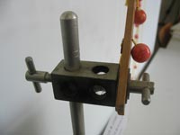
stand so that the angle
between the two can be
adjusted
- At a small distance from one end of the ruler (I used 3 cm), drill a hole through the ruler, with which to fasten it to the clamp stand.
- Drill 20 holes (I used a diameter of 2.5 mm) at intervals of 5 cm in the ruler, the first one 5 cm from the hole drilled in step 1.
- Attach the ruler to the clamp stand. The angle between the two needs to be adjustable, so fasten the ruler on a pivot – I used a clamping boss and two rings to do so (see image).
- For each of the 20 holes, calculate the corresponding length of string required (see Table 1). Allow about 5 cm extra – for attaching the string to the bead and the ruler – and cut the strings.
- For each string, tie a bead to one end, pass the other end through the corresponding hole in the ruler, and attach it by threading the string through a paperclip that will act as a stopper (see image). Do not use sticky tape instead of the paper clips, as this will gradually work itself loose.
-
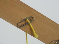
Fasten the strings to the
ruler by threading them
through paper clips
Images courtesy of Elias
KalogirouAdjust the strings to exactly the calculated length.
The model is now complete. As a guide, it took me about two hours to build.
Calculating the lengths of string
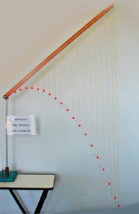
model
Image courtesy of Elias
Kalogirou
To understand how we calculate the lengths of the strings, we need to understand what the model represents. Imagine that at time zero, you fired a bullet at steady speed (no horizontal acceleration) from the pivot point (connecting the ruler and the clamp stand), in the direction that the ruler is pointing in.
The model demonstrates two aspects of a trajectory. Firstly, the direction in which the ruler is pointing gives the direction in which the bullet would continue flying if there were no gravity.
Secondly, the strings represent the effect of gravity (g). If you let the bullet drop from the pivot point at time zero (vertical fall without initial velocity), the length of string of the first bead would give the distance the bullet would have fallen after time t, the string of the second bead would give the distance the bullet would have fallen after 2t, and so on (see Table 1).
Gravity has the same effect on a projectile with an initial velocity greater than zero, so when you shoot the bullet rather than letting it drop, it would still fall the same distance by time t.
For an initial velocity greater than zero, the length of the first string again gives the distance the bullet would have fallen after time t, the second string gives the distance the bullet would have fallen after 2t, and so on. The beads, therefore, represent the parabolic trajectory of a projectile, with the angle of the ruler to the stand representing the starting angle of the projectile.
The positions of the 20 beads, hanging 5 cm apart, give you the positions of the bullet at 20 equidistant consecutive time points – the first bead at time t, the second bead (5 cm further along the ruler) at 2t, and so on, up to the last bead, at 20t.
The model represents trajectories at constant horizontal velocity (including zero, if you place the ruler in a vertical position, parallel to the stand) and constant vertical acceleration. Once you have chosen your value for t, cut the strings and built the model, it will be a model for trajectories with this specific value of t, i.e. also for a specific velocity and acceleration (gravity) – at different angles, depending on how you position the ruler, and disregarding air resistance. How closely the model reflects reality could be an interesting point for discussion with your students.
The length of the shortest string, at time t, is calculated as:
a = ½ g t2.
To calculate its length (a), choose the maximum length of string for bead number 20, which is 100 cm from the pivot point, and corresponds to 400a (see Table 1). Our longest string (400a) was 145 cm, so a = 0.3652. Then you can calculate the lengths of string you need to cut for the 20 different beads using the ‘String length’ column in Table 1 (and do not forget the 5 cm extra when cutting, see step 4 above).
Using the model in class
The actual construction of the model is already a valid act of learning in itself. In addition, the finished product can be used for further work. It can be used to study either horizontal or vertical trajectories, as well as those at any angle in between. Below are some suggestions – there will be plenty of others.
Experiment 1
In this experiment, students learn that the horizontal and vertical components of a trajectory are independent of each other, with the horizontal velocity remaining constant during the ‘flight’.
- Ask the students to position the ruler so that it is held horizontally (at 90 degrees to the clamp stand). The beads now indicate the positions of a projectile that has an initial horizontal velocity but no initial vertical velocity (like a coin flicked horizontally off a table top).
- Ask the students to estimate how long it would take for a projectile to move from the starting position (the pivot) to the first bead (or indeed from any bead to the next). Any time that is less than one second will be fine.
Next, we will try to get this number closer to a true figure – which will of course vary depending on how quickly the projectile is launched. - Get the students to ‘flick a coin’ alongside the model, trying to get the coin to travel a horizontal distance similar to the length of the ruler, and time how long it takes before the coin lands. Dividing that time by the number of beads the coin has passed will give an approximate interval for the flight time between successive beads, ignoring air resistance. The longer the trajectory, the less significant any timing error should be.
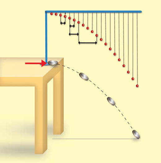
Image courtesy of Marlene Rau and Nicola Graf
- With this figure for the time interval, ask the students to calculate the horizontal velocity for a few pairs of beads (both consecutive ones and pairs of beads that are further apart, e.g. between bead 3 and 4, then between beads 3 and 15 – make sure that the students remember to use the appropriate time interval if using non-consecutive beads in the pair), using horizontal velocity = horizontal displacement / time interval: vhoriz = hhoriz / t.
Make sure that the students measure the horizontal distance between bead pairs, not the diagonal distance. If the model has been built accurately, they should find that the horizontal velocity is constant.
Students may be familiar with the average velocity formula, but less so with the idea of dividing up a motion into small time intervals. Therefore, it could be worth having them calculate the average horizontal velocity = total horizontal displacement / total time. This should, of course, equal the velocities worked out from adjacent bead positions.
- Ask the students which assumption we are making when we assume that the horizontal velocity of a projectile is constant. The answer should be that air resistance can be ignored.
Experiment 2
In this experiment, students learn that the horizontal velocity will still be constant for a trajectory with initial vertical velocity (i.e. at an angle away from the horizontal), but it will be smaller than that for a trajectory with no initial vertical velocity (as in Experiment 1).
- Position the ruler of the model at an angle away from the horizontal. I would suggest using a fairly steep angle so that students come up with a noticeably different horizontal displacement to that in the first experiment.
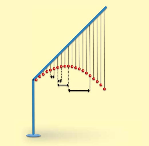
Image courtesy of Marlene Rau
- Using the value for t that you have calculated in Experiment 1 – or the value for t used to build the model, – ask the students to repeat the calculation of the horizontal velocity, as in step 4 of Experiment 1.
Again, if the model has been built accurately, the students should find that the horizontal distance travelled in equal intervals of time is constant, but it will of course be smaller than that for a trajectory with no initial vertical velocity (Experiment 1) – the strings of adjacent beads will be closer to one another.
Experiment 3
In this experiment, the students study the vertical distances travelled in equal intervals of time for a trajectory with no initial vertical velocity (such as in Experiment 1). The experiment is best suited to students who were not involved in building the model, although it can be useful reinforcement for those students, too.
- Return the ruler to a horizontal setting.
A change in the vertical velocity is an acceleration (a), and from the equation F = m a we know that a resultant force is needed to produce such an acceleration – in this case the force of gravity acting on the object. As this force is constant, from equations of uniformly accelerated motion, we get
vertical distance travelled (s) = (u t) + (½ a t2)
where u = initial velocity.
As the initial vertical velocity (u) is zero, (u t) can be ignored, and as ½ a is a constant, the relationship tells us that vertical distance travelled is proportional to time squared. It may be worth pointing out that acceleration (a) and gravity (g) are interchangeable in this context, both representing the acceleration of freefall.
- Ask students to calculate the elapsed time for each bead position (note that at the pivot, t = 0) – this will be 1t for bead 1, 2t for bead 2, etc. (see Table 1), using the value for t built into the model.
- Let the students measure the lengths of strings at different positions – if time is too short to measure all 20, get them to measure at least the shortest and the longest strings, and 3 strings in between – and note down the values. This is the vertical distance fallen at each point.
- Get the students to plot vertical distance travelled against elapsed time squared (i.e. t2 for point 1, (2t)2 for point 2, etc.) for each of the positions measured including point zero.
Instead of using the value for t built into the model, students could use the value calculated in Experiment 1. If this does not correspond to the value of the model, the graph will still be the expected straight line, showing the same correlation, but only above the second point in the graph.
Experiment 4
This simple experiment serves to reinforce the fact that the vertical and horizontal components of a velocity are independent of each other.
- Place the ruler at a 45 degree angle to the stand.
- Students should satisfy themselves that the vertical displacements are of course unchanged, i.e. the distance from any particular bead to the ruler will always be the same, irrespective of the angle at which the ruler is held, as the lengths of the strings have not altered.
Further ideas
These are further questions you can ask the students to investigate:
- What angle to the horizontal will give the greatest horizontal displacement on level ground? What if the ground is not level?
- How could the model be adapted to account for planets where the acceleration due to gravity is smaller or greater than the 9.8 m/s2 on Earth?
- Can the students determine instantaneous vertical velocities by taking pairs of readings from the rulers held at an angle? Can they use these velocities to see how close the model shows an acceleration due to gravity of 9.8 m/s2?
- Does the determination of vertical acceleration change with the angle at which the ruler is held?
Resources
- Freier GD, Anderson FG (1981) Demonstration Handbook for Physics (2nd edition). College Park, MD, USA: American Association of Physics Teachers. ISBN: 9780917853326
- To view an animated demonstration of the projectile motion, see: www.phy.hk/wiki/englishhtm/ThrowABall.htm
- Wikipedia has a good explanation of the trajectory of a projectile, especially the section ‘Angle θ required to hit coordinate (x,y)’: http://en.wikipedia.org/wiki/Trajectory_of_a_projectile
Review
The idea behind the model-building experiment proposed in this article is very creative, and the students will learn through active participation, using many skills along the way. Once constructed, the model will also serve as a visual aid for theory covered in class; this is complemented by suggestions for a set of activities that can be performed during the lesson.
Depending on their students’ abilities, teachers may choose to leave the discovery of the theories behind the experiments to their students, or guide them on their way.
The activity would definitely fit into the physics curriculum, as part of teaching motion (projectiles), a topic included in most European curricula. The activity can be considered as interdisciplinary, since the construction of the model involves the students’ design and technology skills. There is also, of course, the mathematical component of the activity.
Jürgen Azzopardi, Malta


