Supporting materials
Instructions on how to set up the apparatus (Word)
Instructions on how to set up the apparatus (Pdf)
Download
Download this article as a PDF


The world’s largest particle accelerator, the LHC, is deepening our understanding of what happened just after the Big Bang. Here’s how to explore the principles of a particle accelerator in your classroom.
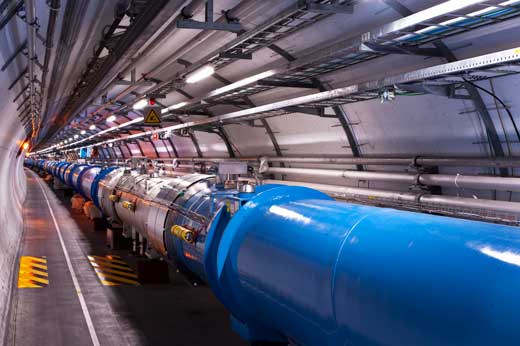
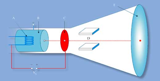
When students think of a particle accelerator, they are likely to imagine the world’s largest ‒ CERN’s Large Hadron Collider (LHC). However, not all particle accelerators are used to investigate the origins of the Universe, nor are they in a 27 km circular tunnel that crosses an international border. Much closer to home is the cathode ray tube (CRT) found in old-fashioned computer and television monitors. A CRT is a linear particle accelerator that creates an image on a fluorescent screen by accelerating and deflecting a beam of electrons in a vacuum (figure 1). And although CRTs are many orders of magnitude less powerful than the LHC, the principles of operation are similar (table 1).
The activities described below enable students to control the same parameters in a CRT as scientists do at the LHC: creating a particle beam, changing the path of the particles and altering their speed. All four activities could occupy a class for at least half a day, but they could also be used separately in individual lessons. For all activities, the particle accelerator needs to be set up as outlined in the worksheet that can be downloadedw1.
See the list of the necessary materials in the downloadable documentw1
A spot is only visible on the fluorescent screen when the cathode is connected. The metal filament heats up and its electrons escape in the form of thermionic emission. The high positive potential of the anode relative to the cathode pulls the electrons into a narrow beam that strikes the fluorescent screen, appearing as a spot.
When the power is disconnected and the cathode is not heated, the electrons cannot escape from the surface because their thermal energy is lower than the energy that binds them to the metal nuclei, sometimes called the work function. Consequently, no electron beam is observed and no spot appears on the screen.
How does this compare to the LHC? Instead of electrons, the LHC accelerates beams of protons or lead nuclei (table 1). The protons, however, are produced using a similar technique to the CRT – in this case with an ion source known as a duoplasmatron. A cathode filament emits electrons into a vacuum chamber containing small amounts of hydrogen gas. The electrons ionise the hydrogen gas, forming a plasma of hydrogen ions (protons) and free electrons. The protons are then confined by magnetic fields and accelerated to become a beam.
See the list of the necessary materials in the downloadable documentw1.
When the voltage to the left deflection plate is greater than the voltage to the right plate, the spot will be to the left of the screen and vice versa.
This is because an electrostatic field is created when a potential is applied across the plates. The negatively charged electrons are deflected towards the positive plate, which makes them follow a curved path within the electrostatic field.
Once the electrons leave the electrostatic field, they travel in a straight line towards the screen, at the angle at which they left the field. The greater the potential applied to the plate, the wider the deflection angle of the beam.
Increasing the voltage to the control grid brightens and sharpens the spot on the screen because the potential difference between the control grid and the anode is greater than that between the cathode and the anode. The electrons released by the cathode are repulsed by the control grid and focused towards the anode, resulting in a fine electron beam.
If you do not have access to a CRT, you could try a comparable demonstration using an old television screenw2.
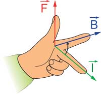
When electrons in the beam pass through the magnetic field, they experience a force at right angles both to the direction in which they are travelling and to the magnetic field. This deflects the electron beam. You can work out the direction of force using Fleming’s left hand rule (figure 3).
Electromagnets produce a stronger magnetic field so the beam is deflected more than by the bar magnet.
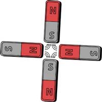
How does this compare to the LHC? The LHC uses superconducting quadrupole magnets to focus the particle beam. A quadrupole magnet consists of four magnetic poles, positioned so that the field lines cancel each other out at the centre (figure 4). When a particle beam passes through the very centre, where there is no magnetic field, it feels no force. The quadrupole magnet, therefore, pushes the beam into a small cross-section, akin to a lens focusing light. However, each quadrupole magnet only focuses the beam in one direction, so to produce a fully focused beam, successive quadrupole magnets at 90° to each other are used.
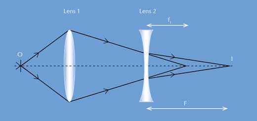
Optical lenses can be used as an analogue for quadrupole magnets. Just as a series of quadrupole magnets at 90° to each other focuses the electron beam in the LHC, combining two lenses of the same focal length (one converging/focusing and one diverging/defocusing) results in an overall increased focal length.
The total focal length F of a system of two lenses with focal lengths f1 and f2 separated by the distance d is given by:
![]()
Because the first lens is focusing and the second defocusing, while their focal length is the same, f2 = –f1. Substituting this into the formula gives:
![]()
The total focal length is increased when two lenses are combined.
When the anode voltage is low, there is no electron beam. As the voltage is increased, the spot becomes visible and then brighter.
Increasing the potential difference between the anode and the cathode (by increasing the voltage to the anode) increases the velocity of the electrons towards the screen.
How does this compare to the LHC? The first electrostatic accelerator of the LHC (located inside the proton source) accelerates protons using a potential difference of 90 kV. However, these protons do not reach the velocity that the electrons in the CRT reach with a lower potential. This is due to the higher mass of the protons. Proton accelerators like the LHC, therefore, need more energy to accelerate particles to high speed.
v = 9.38 × 10⁶ ms-1

The European Organization for Nuclear Research (CERN)w3 is one of the world’s most prestigious research centres. Its main mission is fundamental physics – finding out what makes our Universe work, where it came from, and where it is going.
CERN is a member of EIROforumw4, the publisher of Science in School.
These activities were developed in Julian Merkert’s thesis during his study at the University of Karlsruhe, Germany, and a two-month stay at CERN. The initial inspiration came from an idea from Prof. Dr Günter Quast at the University of Karlsruhe to “explain particle physics with school experiments”.

We have all heard about CERN and the particle acceleration experiments conducted there. However, for some it may seem like a place that is very far from the classroom. Despite this physical distance, the project described in this article succeeds in reducing the barrier between the scientists’ working place and the students’ classroom.
The procedure for setting up the apparatus is very detailed, hence making it accessible to teachers. While ensuring that every part of the project is explained in terms of the physics theories involved, the authors have also compared the LHC with the CRT throughout the article. This makes it extremely interesting, apart from being highly instructive.
This article can give rise to a discussion about the work being done at CERN, linked with the origin of the Universe, the progress we have made so far in the exploration of this theory, and the certainties and uncertainties surrounding it!
Catherine Cutajar, Malta